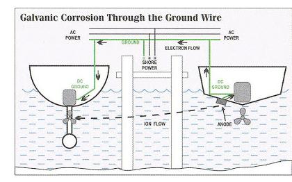
Galvanic IsolatorWhen it comes to corrosion, there’s some misunderstanding, particularly about the role that shore power connection plays. With very rare exceptions, 120- and 240-volt AC shore power doesn’t affect corrosion of the zinc anodes or underwater metals. Corrosion is primarily a DC phenomenon. However, the shore-power cord, with its yellow-green safety ground wire, often plays an accessory role. Galvanic Corrosion through the Shore Power Ground Wire
By plugging the AC shore-power cord into the corresponding dock pedestal,
an electrical connection between the grounding system of the vessel
(including the grounded underwater metals, zinc anodes, seacocks, shaft, strut,
and so on) and the dock’s AC safety ground is made.
Since the neighbouring boats also use the same earth connection, this effectively
connects all the boats and their underwater metal parts together via the earth
cables in the shore power leads.
Unfortunately as all the boats (and metal pontoons) are now interconnected via the
earth cables, any voltage leaks or "galvanically" generated voltages have an easy path
between the boats.
This often results in rapid loss of sacrificial anodes and increased corrosion
of all underwater metals. Semi-Conductor Isolator
Instead of removing the ground connection, a galvanic isolator can be installed.
This device is inserted in line with the yellow-green safety ground wire as it enters the vessel,
typically between the shore-power inlet and the electrical panel.
Its simple mission is to allow AC fault current to pass unimpeded while blocking,
to a degree, DC current.
With this approach, AC faults are safely conveyed back to their source while
destructive galvanic DC current is hindered.
With a galvanic isolator in place, the zinc anodes protect the ship's underwater
metals but not those of the other vessels.
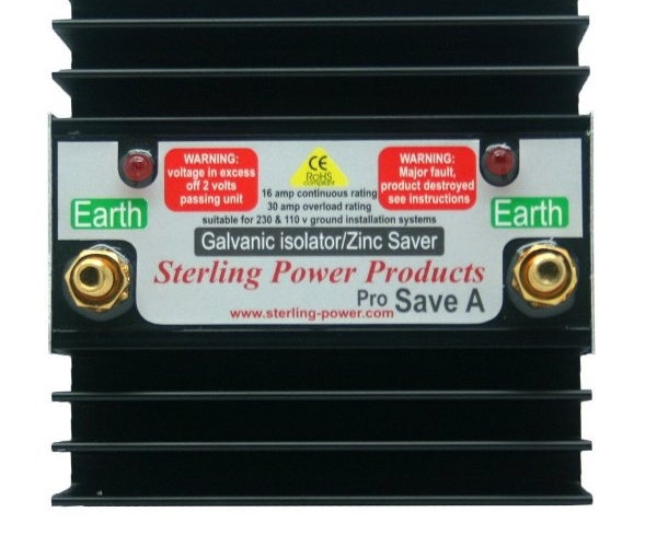
The above picture shows an example of a semi-conductor based galvanic isolator. The four silicon diodes are mechanically fixed on a large heat sink to guarantee sufficient heat dissipation that prevents them from premature thermal failure. It is important to understand, that a galvanic isolator does not replace the sacrificial zinc- or aluminium anodes which are essential to protect the underwater metal parts. A galvanic isolator does offer protection from AC stray currents as well as galvanic DC currents which attack the boat's galvanic zinc protection via the shore power earth cable. These currents can originate from neighbouring boats, metal pontoons as well as leaks on the AC 120/240 volt systems in the marina. Without galvanic isolation and even with protective anodes, serious DC leaks can devastate the propellers, shafts, seacocks and so on, in a matter of weeks (after first having depleting the anodes). Aluminium HullsAluminium hulls have a galvanic potential of -0.75 to -1.0 depending on the alloy, temperature, salinity and water movement. Conventional galvanic isolators provide only about 1.2 volts of isolation so protection is degraded to stray AC or DC when used for aluminium hulls. Connecting two galvanic isolators in series will provide approximately 2.4 volts of isolation to isolate low electrolytic voltages from the dock but still pass safety currents to ground in the event of a short circuit, or power leakage on the boat. Testing Semi-Conductor IsolatorsThere are two ways for a diode-based isolator to fail: either the diodes are shorted, or they are blown open circuit. Both failures can be tested with a digital volt meter that can read positive and negative voltages (with internal rectifier function). With the voltmeter on the DC range, and connected across the shore power side and the boat side connectors of the isolator, there should be some residual electrolytic voltage (unless the ground connection to the shore power facilities is missing), so the meter should read something in the range of one volt. If it always reads zero, the diodes are shorted out. If it reads greater than about 1.2 volts then the diodes are open circuit. This check should be repeated with the meter switched to AC volts, since if some AC current is flowing, the DC meter setting may not show any activity. Isolation Transformer
Isolation transformers and galvanic isolators represent two very different methods of
achieving the same effect: isolating the boat from low voltage DC galvanic currents
that can cause corrosion to underwater metals and excessive wasting of sacrificial anodes.
Isolation transformers achieve isolation by providing an electromagnetic connection between the boat and the dock.
The shore power goes to the primary windings of the transformer when it generates an electromagnetic field
that is picked up by the secondary windings and serves the boat.
No actual wire connects the primary and secondary windings, and no DC current can pass between the two sides.
The shore ground wire stops at the transformer primary, and new ground wire can be made at the secondary windings.
Isolation transformers are big, heavy and expensive, but the transformer is more resilient to
surges and lightning.
Although, it could still be damaged by a direct hit, it is less likely to be damaged by a power
surge due to lightning down the line.
Modern galvanic isolators are almost always of the "fail safe" kind.
But this doesn't mean they can't fail, it just means that if they do they will fail in the
closed position and will maintain the safety ground even if they do not maintain galvanic isolation.
If a transformer is damaged in a lightning strike it probably won't function at all.
So in also terms of reliability, the transformer is preferable over a semi-conductor based galvanic isolator.
|
 It suffices, if one of the neighbouring vessels has depleted or defective zinc anodes.
In this case, through the ground connection, your intact anodes will protect both vessels,
or even several vessels, until your anodes are also depleted, which may happen very rapidly.
It suffices, if one of the neighbouring vessels has depleted or defective zinc anodes.
In this case, through the ground connection, your intact anodes will protect both vessels,
or even several vessels, until your anodes are also depleted, which may happen very rapidly.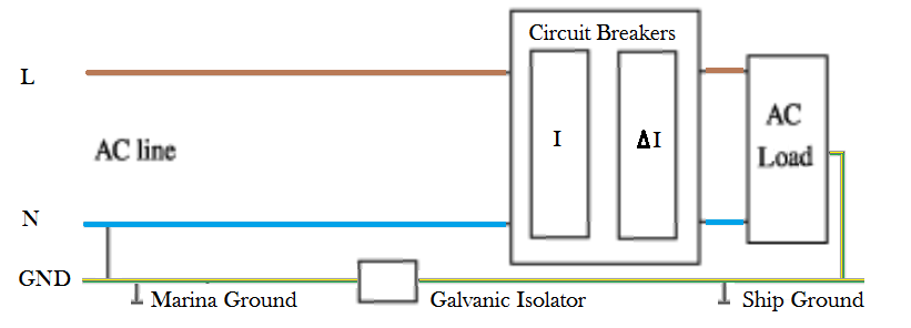 The galvanic isolator relies on the fact that electrolysis voltages are
quite low - usually less than one volt - whereas electrical failure voltages
are quite high.
Silicon diodes, which are used to conduct electricity in one direction but
block it in the reverse direction, have a built in forward voltage drop of
about 0.6 volts, which increases only slightly while conducting higher currents.
Since the fault current an AC fault, it must be able to flow in both ways.
So, two diodes are placed in parallel pointing opposite directions.
This way, there is always one available to conduct AC current at high voltage,
but at low voltages (around 1 Volt), both diodes are non-conducting and
no electrolytic current can flow.
Depending on the metals involved, electrolytic voltages can be higher than diode drop voltage of 0.6 volts.
Therefore, a good galvanic isolator should have two diodes in series in each direction to give a
1.2 volt isolation.
The galvanic isolator relies on the fact that electrolysis voltages are
quite low - usually less than one volt - whereas electrical failure voltages
are quite high.
Silicon diodes, which are used to conduct electricity in one direction but
block it in the reverse direction, have a built in forward voltage drop of
about 0.6 volts, which increases only slightly while conducting higher currents.
Since the fault current an AC fault, it must be able to flow in both ways.
So, two diodes are placed in parallel pointing opposite directions.
This way, there is always one available to conduct AC current at high voltage,
but at low voltages (around 1 Volt), both diodes are non-conducting and
no electrolytic current can flow.
Depending on the metals involved, electrolytic voltages can be higher than diode drop voltage of 0.6 volts.
Therefore, a good galvanic isolator should have two diodes in series in each direction to give a
1.2 volt isolation.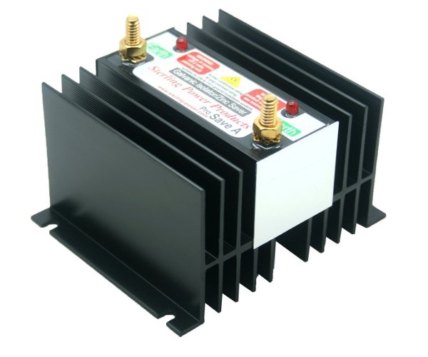
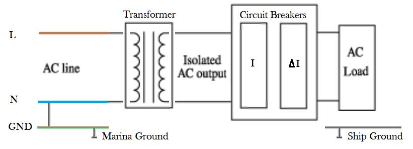 The secondary supply of the isolator transformer must be secured with the normal over-current circuit breakers
as well as a (double pole) residual-current circuit beaker (also called ground fault circuit interrupter).
The residual-current circuit beaker will disconnect the secondary AC supply if an
unbalanced electrical current is detected in the main supply wires. Any such current difference
in the main wires indicates leakage current, which is a potential electrical shock hazard.
However, a residual-current circuit beaker does not protect against unexpected or dangerously high current
(e.g. short circuit failures) and cannot replace the standard over-current circuit breakers (fuses).
The secondary supply of the isolator transformer must be secured with the normal over-current circuit breakers
as well as a (double pole) residual-current circuit beaker (also called ground fault circuit interrupter).
The residual-current circuit beaker will disconnect the secondary AC supply if an
unbalanced electrical current is detected in the main supply wires. Any such current difference
in the main wires indicates leakage current, which is a potential electrical shock hazard.
However, a residual-current circuit beaker does not protect against unexpected or dangerously high current
(e.g. short circuit failures) and cannot replace the standard over-current circuit breakers (fuses).| Cover << Sail Away << Corrosion << . | . >> Sources | last updated: 22-Mar-2018 |