Recharging Lead-Acid Batteries
Keeping lead-acid batteries properly charged is the key issue to
maximize the performance and lifetime of the battery.
Overcharging will lead to loss of water in the electrolyte and subsequent
corrosion of the uncovered parts of the battery plates, whereas
the lead-oxide (PbSO4) that is not removed from the
battery plates due to systematic undercharging will start to christaline
eventually making part of the plates inactive.
Both negative effects will result in irreversible damage of the
battery plates.
The way in which the recharging process is performed is directly related
to the reliability and lifetime of the battery system.
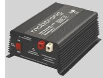
Ideally each battery should be recharged with a battery charger, which
is optimized for this specific battery. Especially the absorption voltages
and float-charging voltages should be applied according to the battery's
data sheet. Even for relative small battery systems as used on board of
vessels, the extra cost for adaptive high-quality battery chargers is easily
compensated by the longer lifetime of the batteries.
General Recharging Scheme
When a lead-acid battery is recharged, electric current is supplied to
the battery electrodes to perform the discharge reversal electro-chemical
process.
Lead-sulphate in the positive electrodes is converted to lead oxide,
and on the negative electrode, is converted to metallic lead,
the sulphuric acid electrolyte goes from dilute to more concentrated.
The lead-acid charging process is somewhat lenient as long as overcharging,
overheating, and excessive gas production is avoided.
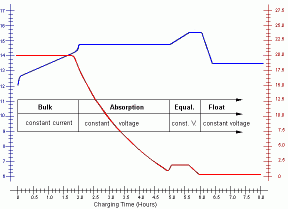
The recharging process is usually divided into four successive phases:
bulk charging: in the first stage the battery is charged
with a constant current.
The current will be in the range of 20% of the battery's Ampere-Hour rating (C/5)
and should not cause overheating (e.g. 10A or lower for a 50Ah battery).
The battery voltage will slowly increase, but should never exceed the
type-specific voltage above which the electrolyte starts producing excessive gas.
As soon as the battery voltage reaches this level, the charging with a
constant current must be stopped.
The battery recharge level is then about 80% of the nominal capacity.
|
 |
absorption charging: in the next phase, a constant voltage is applied
to the battery electrodes.
The rate at which the battery continues to absorb charge in this mode
gradually slows down.
The charging current will decrease until the battery is fully charged.
The voltage applied at this stage depends on the battery type and is
typically 14.2 to 15.5 V.
At the end of this phase the charging current drops below 1% of the
battery's Ampere-Hour rating (C/100; e.g. 0.5A or lower for a 50Ah battery).
At this state the 95% recharged state is normally obtained.
equalization charging: this phase is optional and should only be
performed for non-sealed wet-cell batteries. Equalizing reverses the build-up
of the chemical effects like stratification up on the plates. During the
equalization phase a controlled 5% overcharge to equalize and balance the
voltage and specific gravity in each cell by increasing the charge voltage
(5% over nominal voltage). During this phase heavy gassing will occur (at
about 2.4V cell voltage @ 25°C). This phase should be supervised carefully.
Equalization has completed once the specific gravity values no longer rise
during the gassing stage (which is hard to check!).
float charging: during this phase the charging voltage is reduced
to typically 12.8V to 13.2V (about 2.2V per cell @ 25°C), and held
constant at this value to obtain and maintain a fully charged battery state.
The applied voltage is chosen such that the float charging can
extend indefinitely without damaging or stressing the battery.
|
The correct values for the absorption and float-charging voltages and
especially for the currents and voltages applied during the equalization
phase depend on the type of battery to be loaded. Moreover these parameters
are different for different battery models and manufacturers.
The basic chemical reaction occurs between the conductive lead grid,
the various oxides and active materials, and the electrolyte.
Depending on the reaction rates, the electrolyte will decompose in to
gaseous components.
The biggest danger to a battery is water loss, ultimately resulting in
the escape of hydrogen and oxygen gasses from the electrolyte during recharging.
This electrolyte decomposition into gas must be kept under control by correct
selection of the voltage values applied to a battery during charging. This
is the reason why different manufacturers recommend different charging
voltages for their batteries.
Ideally the battery charger should apply the correct charging parameters
(voltages and currents) according to the battery's data sheet or according
to the manufacturer's recommendations.
Recharging Wet-Cell Batteries
Non-sealed lead-acid batteries should not be recharged with high charging
currents because in contrast to the sealed versions, non-sealed batteries
will show excessive gassing during rapid recharge.
Charging at 15.5V will give a 100% charge. Once the charging
voltage reaches 2.583V per cell, charging should be stopped or reduced
to a trickle charge (float charge). Note that wet-cell batteries must
"bubble" somewhat to obtain full charge, and to mix the electrolyte. Float
voltage should be about 2.2V per cell, or about 13.2V for a 12V battery.
sealed batteries
Where non-sealed lead-acid batteries have the situation of excess gassing
during rapid recharge, the sealed types do not. This lends itself to higher
rates of recharge without damage or reduction of life. Complete charge
times of less than 1 hour are possible. Nevertheless most battery chargers
will limit the charging current in order to minimize the power dissipated
in the charger.
When float charging at 25°C, the cell voltage should be maintained
at a range between 2.2 and 2.4V. Exceeding 2.4V may cause accelerated grid
corrosion. The temperature affects what the optimum charge voltage should
be. For higher temperatures, the chemical reactions are more active and
therefore the voltage should be reduced to or below the 2.3V range. For
lower temperatures, the voltage must be increased to a range exceeding
2.4V to obtain completed charging.
Recharging Gel-Cell Batteries
Generally the charging current (bulk charge) for gel-cell batteries
should not exceed the "C/20" rate or 5% of the capacity. The charging voltages
(absorption and float) should be 20% lower than the voltages for wet-cell
batteries.
If overcharged, voids can develop in the gel, which will never heal,
causing permanent loss in battery capacity. The charging current and voltages
must be strictly limited to the manufacturers specification. To obtain
a reliable full charge state, special battery-specific charge controllers
may be required.
Recharging AGM Batteries
Nearly all AGM batteries are "recombinant" meaning that the oxygen and
hydrogen recombine inside the battery. These use gas phase transfer of
oxygen to the negative plates to recombine them back into water while charging
and prevent the loss of water through electrolysis. The recombination is
typically 99% effective, so almost no water is lost.
Charging voltages are the same as for any wet-cell battery. There is
no need for any special adjustments or problems with incompatible chargers
or charge controls. And since the internal resistance is extremely low,
there is almost no heating of the battery, even under heavy charge and
discharge currents. Some AGM batteries don't even have a maximum charge
and discharge current limit specified.
The charging of AGM batteries can be done by applying a constant-voltage,
where the charging voltage is held to a range of 2.3 to 2.6V (at 25°C)
and the current is allowed to vary. This lends itself to higher rates of
recharge without damage or reduction of lifetime. Complete charge times
of less than 1 hour are possible (C/1 rate). Nevertheless most battery
chargers will limit the charging current in order to minimize the power
dissipated in the charger and the cables.
Since the voltage drops over the cables may be significant for high
charging currents, AGM battery chargers should have an extra pair of wires
for "voltage sensing" directly at the battery connections.
AGM batteries may be equalized twice a year by following the manufacturers
specifications.
Charge Controllers for Marine Power Systems
A charge controller is a regulator that connects an electrical power source
(e.g. power line, alternator, wind generator or solar panel) to the batteries.
Regulators are designed to keep the batteries properly charged at peak without
overcharging.
Monitoring meters for charging currents and battery voltage are included with
most types.
Especially for marine installations, multiple power sources will have to be
integrated into the battery recharging strategy.
One feasable solution to obtain this is to use a high-quality charger
that can work on an DC input voltage of 10-16 volts (e.g. a solar charge controller)
and to adapt the available power sources to this voltage range by high-efficiency
AC/DC- and DC/DC-converters.
 Modern charge controllers are based on the same technology as used in
switch-mode power supplies. They can be easily designed to accept a wide
range of input voltages while retaining an optimal charging performance.
Based on the same technology, AC/DC converters can be designed to adapt
the wide range of line voltages (typ. 80-250V) and frequencies (typ. 40-200Hz)
in use worldwide, to the required DC input range for the battery charger.
Such high-quality battery chargers allow to program the characteristic
parameters of each of the recharging phases such as bulk-load current,
absorption, equalization and floating voltage.
They will also be temperature controlled, adapting the recharging
parameters to different environmental conditions. In this way the
optimal charging algorithm can be used for the connected battery system.
In order for temperature control to work properly, a temperature
sensor must be available, which must be thermally connected to the
battery before the charging is started.
In the data sheets of battery chargers the "Bulk-Absorption-Float" algorithm
is usually described as "I-Uo-U"-algorithm referring to the characteristic
parameters of each of these charging phases (bulk-charge current, absorption-
and float voltage). Usually these chargers do not automatically include an
equalization phase in a their normal recharging algorithm.
In some models, equalization can be initialized manually as an extra recharge
phase.
If the on-board power system consists of a multiple-battery pack, a
charger with multiple outputs should be used to recharge such a system.
This enables that each battery will be recharged individually with the
optimal recharge rate. In such a system the temperature control will work
reliable only if each battery has its own temperature sensor.
Some vendors of high-performance battery charges are:
Alternatively a separate AC-DC converter (isolator) fed from the land-based power line, can be used to
generate a resilient on-board 12V supply, which can feed the solar- or wind charge controller.
Some vendors of high-performance AC-DC converters are:
Notice: high-load AC-DC converters may exhibit high inrush currents (e.g. Powersolve 1500W model
has up to 45A @ 230VAC).
Most marina or pier power installations will not accept such high peak currents (typical value
will be 16A @ 230V).
|

 Modern charge controllers are based on the same technology as used in
switch-mode power supplies. They can be easily designed to accept a wide
range of input voltages while retaining an optimal charging performance.
Based on the same technology, AC/DC converters can be designed to adapt
the wide range of line voltages (typ. 80-250V) and frequencies (typ. 40-200Hz)
in use worldwide, to the required DC input range for the battery charger.