Bygrave's Slide-Ruler for Sight Reduction
|
Sight Reduction is the process of solving the Navigational Triangle
for an Assumed Position and the position of an observed Celestial Body
in order to obtain a Line-of-Position.
The basic underlying problem is solving the trigonometric relations
of a spherical triangle. Since this problem arises not only in earth-bound
navigation but in a variety of fields such as astronomy and geodesy, it
was a popular research topic for mathematicians for over centuries.
In the seventeenth century, John Napier (1550-1617) proposed a method of
solving the oblique navigational triangle by dividing it into two
right-angled triangles, which can be solved with less complex
trigonometric operations.
Unlike the use of the spherical laws of cosines, Napiers Rules involve only
products and quotients of trigonometric functions, and are thus very practical
for logarithmic computation. Since also the principle of logarithms, was
first developed by John Napier, he provided a complete practical toolbox for
solving mathematical problems related to spherical triangles.
In the beginning of the 20th century while serving with the R.A.F, Captain
Leonard Charles Bygrave
developed a method based on the Napier solutions for right-angled triangles,
suited to be solved with a mechanical slide ruler. This made the method faster than the
table-based methods such as Ageton's. Although the level of achievable accuracy
is lower than some table-based methods, in aviation, the required time to get the
Sight-Reduction problem solved is of higher priority than accuracy.
Nevertheless, by using an ingenious system of spiralling scales printed on concentrically
rotatable cylinders, and given a good mechanical implementation, the accuracy of the
Bygrave slide ruler can be remarkably high and the device has proven it's practical
suitability for many decades.
|
|
In the nineteenth and twentieth century many sets of equations have been
developed for the sight-reduction problem. Each set was tailored for some special
way of solving this trigonometric problem either for special table-based solutions
(e.g. A. Ageton)
or as in the case of Bygrave for a mechanical (vernier based) computing device.
|
Solving the divided Navigational Triangle
Through the process of sight-reduction a solution for the Navigational Triangle
is obtained (yielding the calculated values for Altitude (Hc) and Azimuth (Zc)).
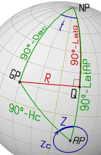
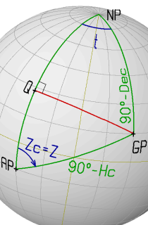
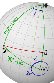
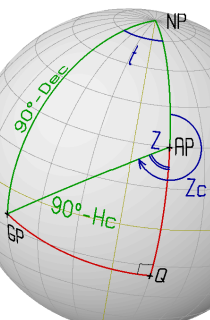
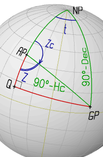
To solve this problem, the oblique Navigational Triangle
between the Geographical Point (GP) of the observed celestial body,
the Geographical North Pole (NP) and the Assumed Position (AP) of the observer
can be divided into two right-angled triangles by a great-circle segment "R"
starting at GP and intersecting the Meridian through AP at a right angle.
This defines a new triangle side "R" and a new triangle vertex point "Q".
This point has the same Longitude as the Assumed Position and
an unknown Latitude "LatQ".
The Method of Bygrave introduces two additional - intermediate - elements in the
divided Navigational Triangle: the Latitude of the vertex "Q" (LatQ) and the
complementary angle of the meridian segment "Q-AP": "Y" = 90°-"Q-AP"
("Q-AP" is the latitude difference between the locations Q and AP; see picture
at the top of this section).
Further, the meridian angle "t" is used instead of the LHA. The meridian angle
is measured from the local celestial meridian to the hour circle of the celestial
body. It is measured positive if the GP is East of the observer and negative
if the GP is West of the observer (see work scheme below).
For the triangle NP-Q-GP use the Napier equation:
cos(a1) = tan(S2)/tan(S3) with a1=t, S2=90°-LatQ and S3=90°-Dec.
This yields: cos(t) = tan(Dec)/tan(LatQ). Since "Dec" and "t" are known,
this can be reformulated to find "LatQ":
tan(LatQ) = tan(Dec)/cos(t) (1)
With LatQ, the value of Y must be obtained from: Y = 90° - LatQ + LatAP.
In both right-angled triangles NP-Q-GP and AP-Q-GP the side "R"
can be calculated with the Napier equation:
sin(S2) = tan(S1)/tan(a1), with a1=LHA, S1=R and S2=90°-LatQ for the first
triangle and with a1=Z, S1=R, S2=90°-Y for the second one.
This gives a set of two equations, from which the common value tan(R) can be
eliminated, yielding:
tan(Z) = tan(t)*cos(LatQ)/cos(Y) (2)
Applying the Napier equation:
cos(a1) = tan(S2)/tan(S3) for the triangle AP-Q-GP with
a1=Z, S2=90°-Y and S3=90°-Hc yields:
tan(Hc) = cos(Z) * tan(Y) (3)
A solution for both the Altitude (Hc) and Azimuth (Zc) may be obtained through these 3 steps.
This requires only a combination of multiplication and division of two different functions:
tangent and cosine. The three steps above can be reformulated in a logarithmic scheme
such that the multiplications/divisions operations reduce to addition/subtraction.
For practical reasons, Bygrave decided to use a cotangent scale on his apparatus
(instead of the tangent scale) and reformulated the above equations
(with cot(x) = 1/tan(x)) to the following set:
          1/cot(Dec) = cos(t)/cot(LatQ)                                     (1)
  cos(LatQ)/cot(t)   = cos(Y)/cot(Z)                                        (2)
     cos(Z)/cot(Y)   =      1/cot(Hc)                                       (3)
Common to the above equations is that, if the value "1" is replaced by "cos(0)",
they all describe a ratio of the form cos(x)/cot(y) on both sides of the equality.
If the equations are processed in the order (1) to (3) as indicated above, the
left-hand-side ratio is known and the right-hand side ratio contains the single
unknown parameter which has to be solved in the cotangent function:
     cos(0)/cot(Dec) = cos(LHA)/cot(LatQ)      -> yields LatQ (and Y)       (1)
  cos(LatQ)/cot(t)   =   cos(Y)/cot(Z)         -> yields Z                  (2)
     cos(Z)/cot(Y)   =   cos(0)/cot(Hc)        -> yields Hc                 (3)
Between step (1) and step (2), the value for Y has to be calculated:
Y = 90° - LatQ + LatAP.
Furthermore, some rules for obtaining the correct azimuth angle must be formulated.
This will introduce further additional processing steps between and after the
above steps (2) and (3).
This is described in detail in the section "calculation scheme" below.
The Slide Ruler and Principle of Operation
|
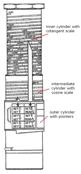
The original Bygrave slide ruler consists of three concentric aluminium cylinders:
The outer cylinder is the "frame" of the device holding the intermediate
cylinder. The two pointers are fixed to this outer cylinder. The intermediate cylinder contains the log cosine scale. The scale
covers the range 0° to 89°40' (and backward, the supplementary range 90°20' to 180°)
over about 22 turns on the cylinder. The inner cylinder contains the log cotangent scale. The scale
covers the range 0°20' to 89°40' (and the supplementary range 90°20' to 179°40')
over about 44 turns on the cylinder.
The cylinders have a diameter of about 55 mm and the total length of the spiralling scales is
about 4.1m and 7.5m for the log cosine and the log cotangent scale respectively.
The scales represent the two functions -log(cos(x)) and -log(cot(x)) plotted in a
linear way such that the log parts can added or subtracted to calculate the multiplication
or division of the primary cosine or cotangent values.
As described above, the slide-ruler apparatus is designed to solve the basic problem:
cos(a)/cot(b) = cos(c)/cot(d)
Of the four variables a, b, c, d, all except for d are known.
The variable d is evaluated by performing the following steps:
align the intermediate cylinder by sliding and rotating, such that the value log(cos(a))
on the cosine scale on the position of the first pointer (the short pointer in the picture). without moving the intermediate cylinder, align the inner cylinder such
that the value log(cot(b)) on the cotangent scale, coincides with the second (long) pointer.
search for the angle c on the cosine scale and move the intermediate cylinder together with the
inner cylinder (keeping both cylinders in the same relative position) such that the value c
is now on the first pointer.
Then read the value d on the cotangent scale at the second pointer.
|
|
The basic idea behind the slide ruler mechanism, is that by keeping a fixed offset
between the two logarithmic scales a constant ratio between the two primary functions cosine and
cotangent is realized. In a certain fixed alignment of the inner- and intermediate cylinder,
any combination of angles c and d read on the two pointers of the cosine and cotangent
scale respectively, will have an equal cos(c)/cot(d) proportion as the angles
a and b initially used to pre-set the two scales.
Different mechanical arrangements are possible to implement the rulers and alignment
mechanism, but all work according to the above principle.
The Bygrave slide ruler has two fixed rulers, one for each scale. For the first step,
each scale is aligned to it's individual cursor, then the cylinders are re-aligned together
as a fixed unit to the known value of the cosine part of the equation and finally,
the result is read at the pointer of the cotangent scale.
The ingenious thing of the Bygrave slide ruler is the cylindrical spiralling scales,
enabling physically long scales, which are required to obtain a reasonable accuracy.
The weak point is keeping the two inner cylinders fixed while re-setting the scales to
the second set of variables.
Unfortunately, Bygrave slide rulers are not produced any more. In the nineteen sixties,
with advances in electronic calculators, the mechanical Bygrave calculator became outdated.
With some effort however, a fully functional - though not waterproof - Bygrave slide ruler
can be made of card board.
Some years ago, Gary LaPook developed a practical flat version of the slide ruler:
http://fer3.com/arc/m2.aspx/New-compact-backup-CELNAV-system-changed-for-archive-LaPook-feb-2009-g7414.
But eventually, a solar-powered electronic calculator operated in transparent zip-bag,
may rather be the preferred twenty-first-century alternative for the mechanical Bygrave calculator.
Calculation Scheme
The calculation scheme shown in the step (1) to (3) is arranged
in such a way that it can easily be solved with the Position-Line Slide Ruler.
Additionally to solving the three angles with the slide ruler, the rules for calculating
the correct values of Y and Zc have to be formulated.
The complete scheme is summarized below. Notice that because of the logarithmic
scale, the slide ruler arrangement will be very inaccurate if angles close to zero occur
in the calculation scheme. In this range the scale is highly compressed and does not
allow for an accurate reading.
In this case the calculation should be repeated with a new observation yielding
a slightly different situation of the spherical triangle constellation, in which all
angles may fit better in the required range.
                                                                              Remarks
     AP:  LatAP  =  ±__°__'_ (N/S)           GP:    Dec =  ±__°__'_ (N/S)       (0)
          LonAP  = ±___°__'_ (E/W)                  GHA =  ___°__'_


     1.   LHA    = GHA + LonAP   =  ___°__'_
            t    =     - LHA     = ±___°__'_         if( LHA < 180°)            (1)
            t    = 360°- LHA     = ±___°__'_         if( LHA > 180°)


     2.   set "0"    ->   set "Dec"    -FIX->       set "t"  ->   read "LatQ"   (x)
            LatQ = ±_______                                                     (2)


     3.   dLat   = LatAP - LatQ  = ________  - ________  = ________

     4.      Y   = 90°   - dLat  =  89° 60'0 - ________  = ________


     5.   set "LatQ" ->   set "t"      -FIX->       set "Y"  ->   read "Z"      (x)
             Z   = ________


     6.   set "Z"    ->   set "Y"      -FIX->       set "0"  ->   read "Hc"     (x)
             Hc  =  __°__

     7.      Zc  =        Z  =                          ___°__     (scheme 1)   (7)
             Zc  = 180° + Z  = 180° 00'  + ________  =  ___°__     (scheme 2)
             Zc  = 180° - Z  = 179° 60'  - ________  =  ___°__     (scheme 3)
             Zc  = 360° - Z  = 359° 60'  - ________  =  ___°__     (scheme 4)


  Remarks and Instructions
  (0)  Use the appropriate signs for Latitude, Longitude and Declination:
       positive for N and E, negative for S and W.

  (1)  The meridian angle "t" is calculated from "LHA" according to the following rule:
       if LHA < 180°   t =      - LHA         (GP is WEST of AP)
       if LHA > 180°   t = 360° - LHA         (GP is EAST of AP)

  (2)  The sign of the Latitude of "Q" (N/S) depends on the values of "t" and "Dec":
       if |t| < 90°   LatQ has the     same sign as Dec
       if |t| > 90°   LatQ has the contrary sign of Dec
       Where |t| is the absolute value of "t"

  (3)  The value of "dLat" must be calculated taking the correct signs for "LatAP" and
       "LatQ" into account. The resulting sign of "dLat" should be recorded correctly
       (see remark 0).

  (7)  The true Azimuth "Zc" is obtained from "Z" according to one of the following
       cases: first select in which range the value of t is, then, depending on the
       sign of LatAP or dLat select the correct calculations scheme for Zc:

       [-180°: -90°]  if LatAP positive:  use  Zc = 360° - Z       (scheme 4)
                      if LatAP negative:  use  Zc = 180° + Z       (scheme 2)

       [ -90°:   0°]  if dLat  positive:  use  Zc = 180° + Z       (scheme 2)
                      if dlat  negative:  use  Zc = 360° - Z       (scheme 4)

       [   0°: +90°]  if dLat  positive:  use  Zc = 180° - Z       (scheme 3)
                      if dlat  negative:  use  Zc =        Z       (scheme 1)

       [ +90°:+180°]  if LatAP positive:  use  Zc =        Z       (scheme 1)
                      if LatAP negative:  use  Zc = 180° - Z       (scheme 3)


  (x)  If an electronic calculator is used to perform the trigonometric calculations,
       the slid-ruler operations:
       set "A"    ->   set "B"    -FIX->       set "C"  ->   read "D"
       may be replace with following sequence on the calculator:
       COS  A   *   TAN  B   /   COS  C  =  shift  TAN  -> read "D"
       with "shift  TAN" selecting the inverse function of TAN (arctangent).
|
This form is also available as printer ready pdf file:
worksheet for Sight Reduction according to Bygrave.
Examples
In the following section, some examples of Sight Reduction
using the Bygrave method are elaborated.
The examples cover typical combinations of Assumed Position (N/S),
Declination (N/S) of the celestial body and possible Meridial Angles.
The operations that would be done using the Bygrave slide ruler in these
examples are performed with an electronic calculator (see remark "(x)" above).
The results are compared to the direct solution of the navigational triangle.
Example 1
 |
AP:  LatAP =  -15° 00'0 (S)          GP: Dec =  +15° 00'0 (N)
     LonAP = -030° 00'0 (W)              GHA =  330° 00'0


 1.  LHA   = GHA + LonAP   =  300° 00'0
       t   =     - LHA     =  ___° __'_
       t   = 360°- LHA     = +060° 00'0   (LHA > 180)

 2.  set "0"    ->  set "Dec" -FIX->   set "t"  ->  read "LatQ"
      LatQ = +28° 11'2

 3.   dLat = LatAP - LatQ  = -15° 00'0 - +28° 11'2 =  -43° 11'2

 4.      Y =  90°  - dLat  =  89° 60'0 - -43° 11'2 = +133° 11'2

 5.  set "LatQ" ->  set "t"   -FIX->   set "Y"  ->  read "Z"
         Z =  65° 51'2

 6.  set "Z"    ->  set "Y"   -FIX->   set "0"  ->  read "Hc"
        Hc =  23° 32'9

 7.     Zc = 065° 51'2
         (t in range [0:90] and dLat negative)
|
|
The following values are obtained when solving the oblique triangle
directly with an electronic calculator:
Hc = 23° 32'9 and
Zc = 065° 51'2.
|
Example 2
 |
AP:  LatAP =  -15° 00'0 (S)          GP: Dec =  +05° 00'0 (N)
     LonAP = +015° 00'0 (E)              GHA =  045° 00'0


 1.  LHA   = GHA + LonAP   =  060° 00'0
       t   =     - LHA     = -060° 00'0   (LHA < 180)
       t   = 360°- LHA     =  ___° __'_

 2.  set "0"    ->  set "Dec" -FIX->   set "t"  ->  read "LatQ"
      LatQ = +09° 55'5

 3.   dLat = LatAP - LatQ  = -15° 00'0 - +09° 55'5 =  -24° 55'5

 4.      Y =  90°  - dLat  =  89° 60'0 - -24° 55'5 = +114° 55'5

 5.  set "LatQ" ->  set "t"   -FIX->   set "Y"  ->  read "Z"
         Z =  76° 07'5

 6.  set "Z"    ->  set "Y"   -FIX->   set "0"  ->  read "Hc"
        Hc =  27° 17'7

 7.     Zc =  360° - 76° 07'5  = 283° 52'5
           (t in range [-90:0] and dLat negative)
|
|
The following values are obtained when solving the oblique triangle
directly with an electronic calculator:
Hc = 27° 17'8 and
Zc = 283° 52'6.
|
Example 3
 |
AP:  LatAP =  +30° 00'0 (N)          GP: Dec =  -10° 00'0 (S)
     LonAP = +015° 00'0 (E)              GHA =  045° 00'0


 1.  LHA   = GHA + LonAP   =  060° 00'0
       t   =     - LHA     = -060° 00'0   (LHA < 180)
       t   = 360°- LHA     =  ___° __'_

 2.  set "0"    ->  set "Dec" -FIX->   set "t"  ->  read "LatQ"
      LatQ = -19° 25'5

 3.   dLat = LatAP - LatQ  = +30° 00'0 - -19° 25'5 = +49° 25'5

 4.      Y =  90°  - dLat  =  89° 60'0 - +49° 25'5 = +40° 34'5

 5.  set "LatQ" ->  set "t"   -FIX->   set "Y"  ->  read "Z"
         Z =  65° 03'7

 6.  set "Z"    ->  set "Y"   -FIX->   set "0"  ->  read "Hc"
        Hc =  19° 51'2

 7.     Zc =  180° + 65° 03'7  = 245° 03'7
           (t in range [-90:0] and dLat positive)
|
|
The following values are obtained when solving the oblique triangle
directly with an electronic calculator:
Hc = 19° 51'1 and
Zc = 245° 03'6.
|
Example 4
 |
AP:  LatAP =  +35° 00'0 (N)          GP: Dec =  +05° 00'0 (N)
     LonAP = -030° 00'0 (W)              GHA =  330° 00'0


 1.  LHA   = GHA + LonAP   =  300° 00'0
       t   =     - LHA     =  ___° __'_
       t   = 360°- LHA     = +060° 00'0   (LHA > 180)

 2.  set "0"    ->  set "Dec" -FIX->   set "t"  ->  read "LatQ"
      LatQ = +09° 55'5

 3.   dLat = LatAP - LatQ  = +35° 00'0 - +09° 55'5 = +25° 04'5

 4.      Y =  90°  - dLat  =  89° 60'0 - +25° 04'5 = +64° 55'5

 5.  set "LatQ" ->  set "t"   -FIX->   set "Y"  ->  read "Z"
         Z =  76° 03'0

 6.  set "Z"    ->  set "Y"   -FIX->   set "0"  ->  read "Hc"
        Hc =  27° 15'5

 7.     Zc =  180° - 76° 03'0  = 103° 57'0
           (t in range [0:90] and dLat positive)
|
|
The following values are obtained when solving the oblique triangle
directly with an electronic calculator:
Hc = 27° 15'5 and
Zc = 103° 57'1.
|
|