Note on Stray Current Corrosion
In order to demonstrate the mechanism and impact of stray current,
the following experiment was conducted:
A pair of electrodes "A" and "B" are used to induce stray current in a
small plastic container filled with clean fresh water.
 A second set of metal plates "C" and "D" represent two of the seawater
connections of a vessel's distributed grounding system.
All the electrodes consist of the same material: galvanised steel, so
without external electrical source, no galvanic potential is present in the set up.
A second set of metal plates "C" and "D" represent two of the seawater
connections of a vessel's distributed grounding system.
All the electrodes consist of the same material: galvanised steel, so
without external electrical source, no galvanic potential is present in the set up.
A power supply connected to the "A" and "B" electrodes
is used to generate the stray current through the water basin.
An amp-meter between the "C" and "D" poles is used to measure the strength of
the stray current and to electrically connect these plates to simulate a distributed grounding system.
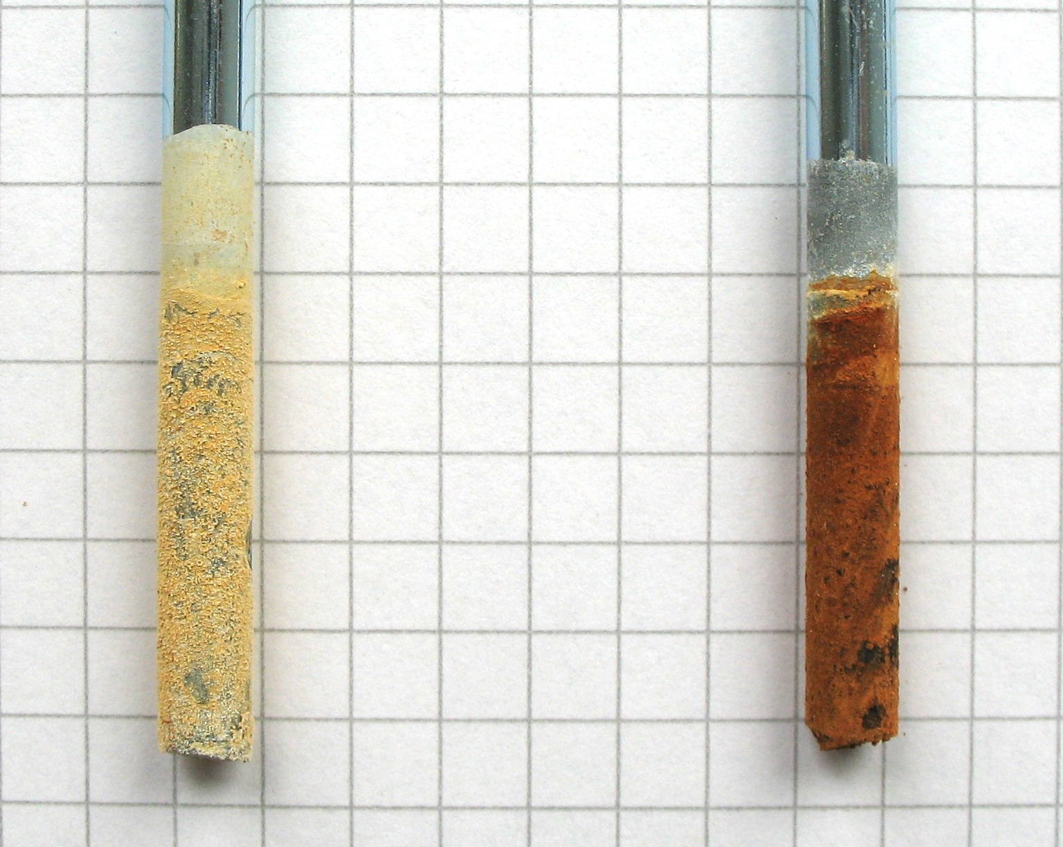
The picture on the left shows the "C" and "D" electrodes after an exposure over 48h at 5 mA stray current.
The electrode on the positive side of the stray path (labeled "D") is the one which is corroded.
It is important to understand that the reason for corrosion comes from outside the (simulated)
grounding system composed of two electrodes "C" and "D".
 The equivalent electrical circuit is shown on the left.
The conductive stray path is indicated with the schematically drawn resistors.
The resistor values and thus the magnitude of the stray current
primarily depend on the water conductivity.
The equivalent electrical circuit is shown on the left.
The conductive stray path is indicated with the schematically drawn resistors.
The resistor values and thus the magnitude of the stray current
primarily depend on the water conductivity.
|