Estimation and Installation of the required Battery Capacity
The electrical power supply on board of small sailing vessels should be planned
carefully in advance of it's installation.
Later changes especially capacity enhancements will often result in serious
installation and reliability problems.
Estimating the Energy Requirements
To plan the battery capacity to be installed, the supply requirements have to
be estimated for different situations.
On a 3-week transatlantic journey, the electrical supply requirements will be
different from the requirements during a 3-week anchoring period.
During anchoring the auto-pilot or GPS receiver will not be used, whereas
under sails, the required energy for the cabin lights may be lower, depending
on how the crew is spending their "off-guard" and "stand-by" periods.
The following scheme should be elaborated for each different situation
(journey under sails, anchoring periods, ...) to determine the worst case daily
energy requirements:
| Electrical Loads |
|---|
Device
|
Power
[W] |
Current
[A]@12V |
Operation
[h/day] |
Energy
[Ah/day] |
|---|
| Refrigerator |
120.0 |
10.0 |
6.0 |
60.0 |
| Autopilot |
24.0 |
2.0 |
18.0 |
36.0 |
| Position Lights |
60.0 |
5.0 |
6.0 |
30.0 |
| Cabin Lights |
120.0 |
10.0 |
2.0 |
20.0 |
| Radar / Plotter |
60.0 |
5.0 |
3.0 |
15.0 |
| GPS receiver |
2.4 |
0.2 |
24.0 |
4.8 |
| Radio TX |
360.0 |
30.0 |
0.5 |
15.0 |
| Water Maker |
60.0 |
5.0 |
4.0 |
20.0 |
| Water Pump |
60.0 |
5.0 |
0.5 |
2.5 |
| Anchor Winch |
1200.0 |
100.0 |
0.2 |
20.0 |
| ... |
... |
... |
... |
... |
| Drained Energy |
- |
- |
- |
250.0 |
| Electrical Generators |
|---|
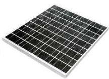
| Solar Pannels |
96 |
8 |
6.0 |
48.0 |
| Wind Generator |
48 |
4 |
18.0 |
72.0 |
| Alternator |
720 |
60 |
1.0 |
60.0 |
| Generated Energy |
- |
- |
- |
180.0 |
|
|
|
|
For each electrical device on board, the daily energy requirement is determined.
Assuming that the power for each device comes from the on-board 12V battery supply,
the power consumption of the device (usually mentioned somewhere on the chassis)
is divided by 12 to obtain the (average) current it draws from the on-board
power supply.
Additionally, the daily time of operation must be estimated.
Consider that electrical devices such as water pumps or refrigerators,
are not continuously active even if they are "switched on"!
So here the effective number of hours the device is really consuming power
must be estimated or experimentally derived by doing long-term
observations.
From this data, the daily required energy [Ah/day] for each device is
obtained by multiplying the current [A] and the daily operation time [h/day].
This is done for each device drawing energy from the on-board power supply
and the sum gives the total energy used daily from this supply.
|
|
The same accounting must be done for the on-board energy sources such
as solar panels or wind generators.
These devices may deliver energy to the on-board power supply and
to the battery system.
But the power output of these generators may vary considerably depending
on the weather conditions (sun, wind, clouds, temperature, ...).
So average values for power and operation time will have to be elaborated
experimentally for this energy account!
It must be taken into account for example that the average power output of
a wind generator will often not exceed 20% of it's peak power!
The same will be true for solar modules, which cannot be optimally
installed on board of a sailing yacht and can be estimated to produce
only about 30%-50% of their nominal power.
The efficiency may decrease even further at higher ambient temperatures
(> 30°).
|
|
Determining the Battery Capacity
For longer journeys without the possibility of recharging the battery
from an external (mainland) power supply, the generated energy should
be higher than the consumed energy.
This requires on-board energy sources such as the alternator
(driven by the in-board engine), solar panels or wind generators!
To provide for some days of battery backup (days with no energy input)
multiply the daily required energy with the number of backup days:
Capacityeff [Ah] = backup-days [days] x daily-required-energy [Ah/day]
This is the required energy that must be made available
for on-board usage.
The installed battery capacity however, must be chosen
about 100% higher:
Capacitybat [Ah] = Capacityeff [Ah] x 2.0
The factor 2.0 accounts for two effects:
only about 60% of the nominal battery capacity should be used regularly
to prevent "over-ageing" of the batteries (providing deep-cycle batteries are used
in the supply system).
due to temperature and ageing effects, the average effective capacity
of a battery system will decrease to about 80% of the original nominal
capacity (as labelled on the batteries).
The energy density of lead-acid batteries is about 35Wh/kg.
For a 12V battery, each Ah of energy results in a battery weight of 0.3kg.
An installation with daily energy requirement of 180Ah and 2 days of
backup will result in 160kg of lead-acid batteries with 540Ah installed
capacity supplying 360Ah effective battery capacity.
Typical cost for a wet-cell lead-acid battery is 1.5 Euro/Ah.
So the total cost for such a battery system will be about
800 Euro.
An equivalent AGM-system will cost about 50% more (2.5 Euro/Ah).
Assembling the required Battery Capacity
The required battery capacity usually can only be obtained by assembling
commercially available batteries in a parallel operation.
The capacity of the parallel battery pack is the sum of the capacities
of the individual batteries.
When connecting batteries in parallel, old and new batteries should never
be mixed and only identical types of battery should be used
(same voltage, same capacity, same type and manufacturer).
Cable lengths should be kept as short possible and the cable size should be
large enough to avoid a measurable voltage drop (less than 0.2V) between the
batteries.
As a simple rule a cable size of 0.05mm2 per effective installed Ah capacity
should be used (e.g. 25mm2 cable size for 540-Ah installed capacity).
Large battery capacities are not very practicable due to the weight
and volume of the required lead-acid batteries.
Therefore another approach would be to rely on the alternator of the
in-board engine to recharge the batteries when no line power from the
mainland is available.
However the loading of lead-acid batteries takes time.
Fast charging with excessive bulk charge currents, will damage
lead-acid batteries.
So if the in-board engine should not run for hours a day just to
recharge the batteries, the only alternative is to reduce the energy
requirements for the autarc periods on sea.
For these periods, the electrical energy supply must be managed in
the same way as water and food supplies are managed.
Obviously, solar panels or wind generators can substantially improve
the energy situation and thus the quality of life on board.
Battery Installation
The in-board boat engine for sailing yachts, normally comes with
a starting battery and corresponding alternator as a complete unit.
The ship builder has - or should have - taken care of special
installation aspects concerning safety, maintenance and the
special maritime environment in which this unit is operating.
The situation for the on-board power supply batteries is usually
different.
Traditionally leisure sailing yachts are equipped with a rather
low battery capacitance for the on-board power supply.
In many cases the battery capacitance will have to be increased
substantially to obtain a "blue-water"-suited sailing vessel.
Since the required battery capacity may finally result in a
large weight of batteries, special attention on the installation
of those batteries should be paid.
Mechanical Installation
Considering the total weight of the required batteries, they should
be installed as low as possible in the vessel and they should
be tightly fixed!
The best position would be in the bilge, just above the keel
provided this is a dry place!
An important aspect is what happens to the batteries if the
vessel is flooding. Safety equipment such as the radio system
should remain operable to broadcast emergency calls.
Also the electric bilge pump should remain under power to work
under such situations.
So the installation of the batteries should be such that the
operation of the on-board power supply system remains fully intact
even in emergency situations.
This can be obtained e.g. by mounting them in an extra compartment,
which should be watertight protecting the system from bilge water
but which must also provide the required amount of ventilation.
Electrical Aspects
Since a power system normally consists of batteries connected in parallel,
the batteries should be placed close together; if possible in close proximity
to the alternator and battery charger.
In any case, the parallel connection and the connection to alternators should
be done with short and properly sized cables.
The cable size should be at least 0.05sqmm per effective installed Ah.
|
 |
Copper cables have a specific resistance of ρ=0.018 Ohm/m/sqmm.
The parasitic resistance of a cable of length L[m] and size d[sqmm] is:
Rcable = ρ * L / d
This resistance will result in a voltage drop over the cable as
soon as electrical current flows through the cable (Vcable =
Rcable * Iload).
This has two consequences:
In low voltage supply networks, the voltage decrease at the load is the
primary design parameter.
Cable sizes should be dimensioned to minimize the voltage drops in the electrical
power system.
Especially the connection between the charging devices and the batteries should
not have a voltage drop of more than 0.1V.
Most regulated battery chargers measure the voltage at their output during charging
and regulate the charging current according to a programmed recharging process.
However, if due to voltage drops between charger and battery, the voltage at the
output of the charger is not identical with the voltage of the battery,
wrong loading currents will be produced, and the battery will not be optimally loaded.
|
The following gives a rough estimation of the expected maximum (average) current
in the power circuit supposing a full charge or discharge in not less than 10 hours:
I10h = effective-installed-battery-capacity [Ah] / 10h
The cable size for the connection between the individual batteries, the alternator
and the battery charger should be dimensioned as follows (provided these
connections are not longer than 2m!):
Acable = 0.50 [mm2/A] * I10h [A]
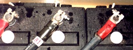
Consider also that physical connections between cables and device terminals
may also have a substantial contact resistance.
These connections must be made with special connectors designed for feeding
high currents.
One characteristic of such connectors is a large contact area with a relative
crumby metal coating, which combined with a high contact pressure,
assures a uniform current distribution over the physical contact area.
Example:
Installed capacity = 540Ah
Effective capacity = 360Ah
I10h = 54A
Acable = 18.0mm2 (Diametercable = 5.0mm)
|
 |
Copper cables have a specific resistance of ρ=0.018 Ohm/m/mm2.
The the resistance of a 10m cable connection with a size of 18.0mm2 is 0.01 Ohm.
Making a closed circuit including the battery charger over this distance
results in a total cable resistance of 0.02 Ohm, yielding a voltage drop
of 0.72V (6%) at 36 Ampere charging current.
This is intolerable, and illustrates the importance of short
and oversized cables for connecting the batteries with the alternator
and the battery charger.
Advanced Battery System for Yachts
The battery system on a typical 40-ft blue-water yacht could consist of the
following components:
a starter battery (80 Ah) for the in-board engine, a heavy-duty service battery (360 Ah) for different "comfort"
applications such as cabin lights, refrigerator, auto pilot and high-power devices such
as inverters and anchor windlass, a safety battery (240 Ah) for safety-related devices such as
radar, HF radio, navigation lights and positioning systems.
The heavy-duty service battery will have the largest capacity and will typically
consist of two identical batteries connected in parallel.
A battery charger with 3 independent outputs will be used for recharging this system.
The negative poles of the batteries are connected to the ground rail through a shunt
(one for each battery system)
Positive poles are NOT connected together. Each battery system operates as an
independent system.
|