Notes on Antenna Impedance
In the following section, some results of the numerical analysis of monopole-
or Marconi antennae will be discussed.
The analysis is biased to the performance at 14 MHz addressing the
HF 20-m band, popular among radio amateurs for long-distance communication.
The analysis was performed with an antenna analysis tool NEC-2 (Numerical Electromagnetics Code)
available from www.nec2.org.
The original code was developed in the 1980s at Lawrence Livermore Labs, under
contract of the US Navy, but has been released to the public later.
The program code is based on the "Method Of Moments" and can be used to simulate
the electromagnetic response of antenna structures.
Current versions of NEC also include ground plane models, so not only free-space
analysis can be performed but also the effects of ground surrounding the antenna
structures may be taken into account for the analysis.
This is an important feature since the characteristics of the ground plane have
a great impact on the (transmission) performance of monopole antennae.
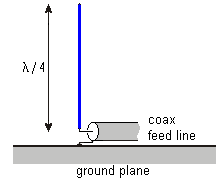
Physical Structure of a vertical Monopole Antenna
Vertical monopole antennae are popular because of their simple design
and omni-directional gain characteristic.
The active antenna part is a simple straight vertical conductor, connected
to the antenna feed line on one side and isolated on the other (top) side.
 Monopole antennae are also known as grounded dipole antennae.
As can be seen from the picture on the right, the ground plane is an
integral part of the monopole antenna and must have an electrical
connection to the braid of the coax feed line.
The ground plane can be considered a an electrical counter part to the single
wire of the antenna and is also called counterpoise.
Monopole antennae are also known as grounded dipole antennae.
As can be seen from the picture on the right, the ground plane is an
integral part of the monopole antenna and must have an electrical
connection to the braid of the coax feed line.
The ground plane can be considered a an electrical counter part to the single
wire of the antenna and is also called counterpoise.
A perfect ground plane is an area of high conductivity below the monopole,
which can be relatively easily obtained on a swimming vessel.
On land a good ground plane is harder to achieve and may require
burried conductors to obtain adequate conductivity.
The quality of the ground plane in terms of area and conductivity is a crucial
point for the antenna performance.
This explicitly includes the connection between the coax braid and the ground plane,
which must be laid out to have low inductance for the frequency range the antenna
is designed for.
It is important to understand, that the monopole feed point has two connections: one
for the active area and one for the counterpoise or ground plane.
Feed-point Impedance of a Monopole Antenna
The first analysis shows the feed-point impedance of a 30-m monopole antenna
with 5 mm diameter over the frequency range of the HF band (3 MHz to 30 MHz).
The gound plane is assumed to be perfect (large area, low conductivity).
This 30-m long monopole represents a quarter-wavelength antenna for 2.5 MHz (120 m).
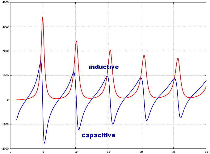
The feed-point impedance Z(f) is the sum of a resistive part (R(f) in red)
and a complex reactive part (X(f) in blue).
The reactive part has a capacitive and an inductive component.
If the reactance is negative, the capacitive component is dominant;
if the reactance is positive, the inductive component is dominant.
The total complex antenna impedance is: Z(f) = R(f) + j X(f).
The above graphs show that this antenna impedance is highly frequency dependent.
For some frequencies the antenna impedance is low and purely resistive (reactive part is zero).
This occurs approximately for the following frequencies: f = 2.5 MHz, 7.5 MHz, 12.5 MHz, ... 27.5 MHz.
For these frequencies, the 30-m monopole antenna is at resonance.
The fundamental frequency for this antenna structure is 2.5 MHz.
It is the lowest frequency for which resonance can be obtained.
The frequencies for which resonance is obtained are the odd multiples of this fundamental frequency.
The corresponding wavelengths are λ = 120 m, 40 m, 24 m, ... 11 m.
At these resonant frequencies, the resistive part of the antenna impedance is about 40 Ohm.
Another conclusion from the above plot is that for the even multiples of the fundamental
frequencies (at approximately 5 Mhz, 10 MHz, ... 26 MHz), the antenna impedance is also
purely resistive, but very high (1000 Ohm and above).
Those two situations can be compared to a series resonance (low resistive impedance) and
parallel resonance (high resistive impedance) of the equivalent RLC-circuit antenna model.
- Bandwidth increased with larger conductor diameter
- Influence of ground plane ("counterpoise")
- Model with segments with distributed R_L_C network.
R: skin effect; L: conductivity of conductor; C: capacity to ground plane.
Mutual coupling (inductive and capacitive) between different antenna segments.
|