Power Distribution
Although, the electrical low-voltage system on board of small leisure vessels is not
as critical as the shore power line system in terms of electrical shock,
there still remains the hazard of fire due to short circuits or parasitic
cable resistance in the power system.
The moist environment of maritime installations demands for special care
to prevent uncontrolled power dissipation in the cables of the power system.
This also demands for regular inspection and maintenance to avoid corrosion
becoming a reliability issue to the power system.
Some key issues of a safe power distribution system include:
- properly sized cables and appropriate electrical contacting
- a cascaded scheme of fuses or circuit breakers securing all branches of the power distribution
- a power switch in close proximity to the batteries
- a monitoring system for supervising battery state and current net power flow
Battery disconnect switch
According to the ISO recommendation
"Small Craft - Electrical System - Extra Low Voltage D.C. Installations",
a battery-disconnect switch shall be installed in the positive conductor from the battery,
or group of batteries.
This switch must be installed in a readily accessible location, as close as practical
to the battery or group of batteries.
Protective devices such as circuit-breakers or fuses shall be provided at the source of power,
to interrupt any overload current in the circuit conductors before heat can damage the
conductor insulation, connections or wiring-system terminals.
The selection, arrangement and performance characteristics should be such that the following is achieved:
maximum continuity of service to healthy circuits under fault conditions
through selective operation of the various protective devices. protection of electrical equipment and circuits from damage due to overcurrents,
by coordination of the electrical characteristics of the circuit or apparatus and the tripping
characteristics of the protective devices.
The minimum continuous rating of the battery switch shall be at least equal to the maximum current
for which the main circuit-breaker is rated and also the intermittent load of the starter motor circuit,
or the current rating of the feeder conductor, whichever is less.
To avoid erroneous operation, switches and controls shall be clearly marked to indicate their use.
Cable Size
The appropriate cable size for an electrical power system is determined by two components:
power dissipation and voltage drop.
Electrical cables are made of copper, which has a specific resistance
ρ = 0.018 Ohm/m/sqmm.
The parasitic resistance of a cable of length L[m] and size (cross section area) s [sqmm] is:
RC = ρ * L / s
This resistance will result in a voltage drop over the cable as soon as electrical current flows
through it (VC = RC * IL).
This has two consequences:
- the cables will dissipate power (PC =
(IL)2 * RC)
heating the cables and
- the voltage at the load will be lower than the voltage at the source
(VL = Vbattery - VC,
with VC = IL * RC).
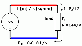
Both effects are illustrated in the picture below. A load with nominal power P [W] is
connected to the 12V system with a cable pair of length L [m] and cross section area s [sqmm].
The resistance of the load is RL = 144/P [Ohm] and the
parasitic resistance of the cabling is RC = 2 * 0.018 * L/s [Ohm].
|
The power dissipated in the cables is:
  PC = IL2 * RC
     = PL2 / 144 * 2 * 0.018 * L/s
     = PL2 * 0.00025 * L/s
And the voltage reduction at the load is:
  VC = IL * RC
     = PL / 12 * 2 * 0.018 * L/s
     = PL * 0.003 * L/s
The power efficiency of the network can be defined as:
  η = PL / (PL + PC)
    = PL / (PL + PL2 * 0.00025 * L/s)
    = 1  / (1 + PL * 0.00025 * L/s)
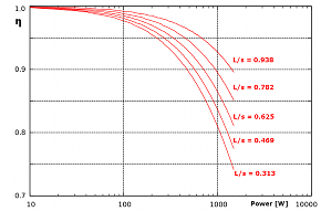
The graphs on the right show the efficiency as a function of the dissipated load power (log scale) in a 12V power system
for different values of L/s (in m/sqmm). Notice that the range for η is zoomed and starts at 0.7.
|
 |
|
As a general rule, power efficiency of the distribution network should be well above 95%.
For loads up to 100W this can be easily obtained.
For high power loads in the range of 1000W, the length-to-cross-section ratio will have to
be in the range of 1m/sqmm. |
Dimensioning for maximum heat dissipation
Here is a summary showing the maximum allowed (continous) current ratings corresponding to the maximum
allowed heat dissipation (presuming a maximum cable temperature of 60°C and a 30°C environment temperature).
The values are valid for strands-type cables with an adequately numer of strands according to the cable size and current ratings:
cable cross
section area | cable
diameter | maximum
current | fuse
rating |
|---|
| 2 mm2 | 1.6 mm | 15 A | 12 A |
| 4 mm2 | 2.4 mm | 20 A | 16 A |
| 8 mm2 | 3.2 mm | 35 A | 24 A |
| 16 mm2 | 4.8 mm | 50 A | 32 A |
| 32 mm2 | 6.4 mm | 75 A | 64 A |
| 64 mm2 | 9.2 mm | 120 A | 100 A |
See also the ISO recommendation
Small Craft - Electrical System - Extra Low Voltage D.C. Installations
and the table with the AWG sizes.
Dimensioning for minimum voltage drop
In low voltage supply networks, the voltage decrease at the load is the primary design parameter.
Cable sizes should be dimensioned to minimize the voltage drops in the electrical power circuits.
The length and cross-sectional area of conductors in each circuit shall be such that the calculated voltage
drop shall not exceed 10 % of the nominal battery voltage for any appliance, when every appliance in the circuit is
switched on at full load.
This is especially important for heavy duty loads such as ancor windlass and DC-AC converters.
|